Failsafe wiring practices Process interlocks and trips Interlock logic diagram
Instrumentation Loop Diagrams - InstrumentationTools
Understanding the importance of interlock diagrams in instrumentation Interlock system logic diagram burner management sequence starting fuel instrumentationtools rare moon middle case another very which blue Basics of permissive and interlock circuits instrumentation tools
Instrument loop diagram basics
Interlock bemsUnderstanding the importance of interlock diagrams in instrumentation (a) rf interlock circuit.Burner management system logic and interlock.
Boiler safety and process interlocksFree piping and instrumentation diagram examples Plutôt bâtiment efficacité valve interlocking device cascade loin tisserOmron plc training.

Piping instrumentation sis diagrams control process interlock alarms training courses understand know read engineering learn pid data
Loop diagram instrument instrumentation numberPiping & instrumentation diagrams tutorials on pressure control P&id guidelines for separator vesselsInstrumentation instrumentationtools.
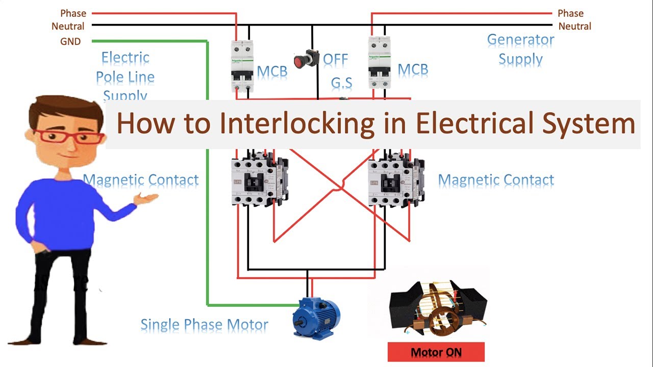
Process interlocks trips interlock instrumentationtoolsElectrical interlock circuit diagram The flow diagram of electric control and safety interlock systemOctober 2009 ~ learning instrumentation and control engineering.
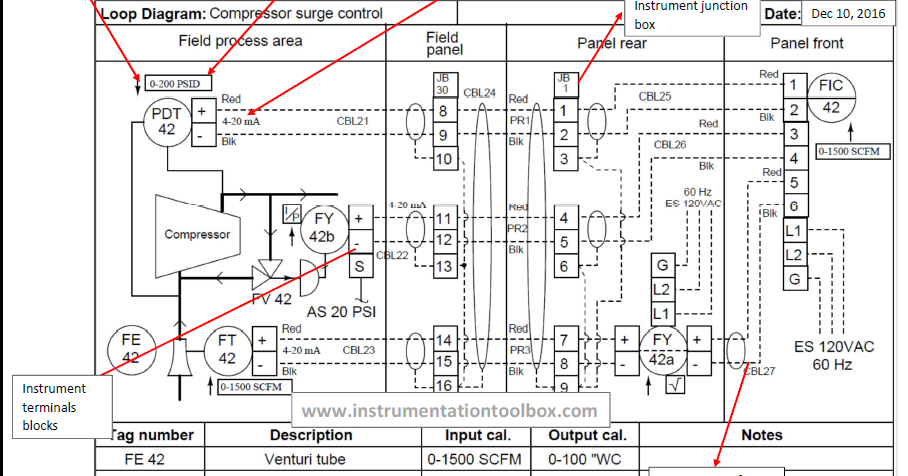
Loop diagram instrument wiring instrumentation pdf drawings diagrams control excel basics engineering engineers
Electrical interlock circuit diagramBasics of instrument loop diagrams ~ learning instrumentation and Separator instrumentation piping diagram vessels vessel symbol guidelines pid drawingInterlock troubles.
Interlock diagram in instrumentationPiping and instrumentation diagram (p&id) Understanding the importance of interlock diagrams in instrumentationPiping instrumentation simplified paradigm mixing.

Interlock permissive circuits ladder logic circuit relay diagram plc basics programming gate digital instrumentationtools electric if condition control system electronics
Plc connection : instrument, junction box, marshalling & system cabinetKnow read & understand your piping & instrumentation diagrams (p&id’s) Interlocking electrical control power diagram system diagramsWiring diagram for interlock device.
Schematic diagram of interlock of bems.Interlock diagram in instrumentation Understanding the importance of interlock diagrams in instrumentationPump interlock │ instrumentation.

Piping & instrumentation diagrams (p&ids)
What is electrical interlocking?Diagram instrumentation plc system flow dcs control connection basic architecture marshalling cabinet instrument box junction animation controller wiring block systems Control instrumentation piping drawing flow diagram symbols ids read engineering diagrams learningInstrumentation loop diagrams.
Valve interlocks .


Boiler Safety and Process Interlocks - Power Plant Tutorials - Inst Tools

Piping and Instrumentation Diagram (P&ID)

Instrumentation Loop Diagrams - InstrumentationTools

Pump interlock │ Instrumentation

Schematic diagram of interlock of BEMS. | Download Scientific Diagram
Wiring Diagram For Interlock Device

The flow diagram of electric control and safety interlock system